A compressed-air vacuum pump turns pressure into a high-speed air jet, then uses that jet to draw air from a suction line and discharge both streams through an exhaust. By following the internal flow and the control sequence, you can distinguish motive-air consumption from useful suction capacity, interpret performance data, and identify whether poor vacuum comes from the ejector, the installation, or the load.
Key takeaways
- Motive air accelerates through a nozzle and lowers pressure at the suction port.
- Additional ejector stages deepen vacuum by removing air from the previous stage.
- Match ejector capacity to the load’s leak rate, volume, and target vacuum.
- Check supply pressure, filters, silencers, seals, and exhaust paths before troubleshooting performance.
How the air jet creates vacuum inside the ejector
A compressed air vacuum pump working process converts supply pressure into jet velocity, then converts that velocity into suction. It does not pull process air into a sealed reservoir. Motive air and evacuated air pass through the ejector and leave through the exhaust during one continuous pass.
1. Compressed air enters the ejector through the motive-air inlet. Its pressure forces the air through a small nozzle.
2. The nozzle narrows the flow passage, accelerating the compressed air into a high-speed jet. As velocity rises, static pressure falls around the nozzle outlet and creates a low-pressure zone at the suction port.
3. Process air from the connected vessel, fixture, or suction line moves toward that low-pressure zone. The pressure difference drives it into the mixing chamber; the jet entrains it by transferring momentum.
4. Motive air and process air collide and mix inside the chamber. The combined stream now contains the compressed air supplied to the ejector plus the air removed from the load.
5. The mixture enters the diffuser, whose widening passage slows the stream. Part of its velocity changes back into pressure so the combined air can discharge through the exhaust.
6. An exhaust silencer reduces noise after discharge, but dirt, oil, water, or scale can restrict it. Backpressure then reduces entrainment and prevents the specified vacuum from being reached.
The ejector therefore consumes compressed air continuously while it operates. Its motive-air consumption is not the same as the suction flow removed from the load.
Why multiple ejector stages reach a deeper vacuum
A second ejector stage does not simply make the first stage stronger; it takes the first stage’s discharge and applies another pressure-conversion step, allowing the suction side to reach a lower absolute pressure.
Each stage repeats three linked actions:
- Nozzle: Compressed air expands through a small orifice, converting supply pressure into a high-speed jet. The jet’s velocity lowers static pressure at the suction entrance.
- Mixing chamber: The low-pressure region draws process air from the vacuum port. The jet transfers momentum to that air, forming a faster combined stream.
- Diffuser: The passage widens and slows the combined stream, converting part of its velocity into pressure before sending it toward the next stage or exhaust.
In a multistage ejector, the first stage removes air from the load and discharges the mixture at an intermediate pressure. The next stage acts on that discharge and reduces the pressure again. Repeating the sequence increases the total pressure ratio, so the pump can approach a deeper vacuum than one nozzle and diffuser can produce.
The trade-off is flow. Extra stages add narrow passages, mixing losses, length, and compressed-air consumption. Those restrictions reduce the maximum volume of air the pump can remove quickly, even while they improve ultimate vacuum.
A single-stage unit therefore suits rapid evacuation at moderate vacuum; a multistage unit suits sealed loads where deeper vacuum matters more than peak suction flow. The industrial compressed air vacuum pump cycle must match that choice to the load’s leak rate.
The operating cycle from start command to shutdown
A start command energises the solenoid valve, admitting compressed air to the ejector. The compressed air driven vacuum pump operation then continues until the vacuum sensor detects the cut-out pressure.
The compressed air vacuum for pump operation steps are:
- The solenoid opens, sending supply air through the nozzle and creating the ejector jet.
- Low pressure at the suction port draws air from the suction line, workpiece, vessel, or leakage path.
- The suction air mixes with the motive air, passes through the diffuser, and leaves through the exhaust with the combined flow.
- The vacuum sensor measures pressure at the application, not simply at the pump inlet, so hose volume, restriction, and leaks affect the reading.
- At the cut-out threshold, the controller de-energises the solenoid and stops motive-air flow.
A vacuum switch uses separate cut-in and cut-out thresholds. That hysteresis prevents a small leak from making the solenoid chatter; without it, gripping becomes unstable and the valve wears quickly.
After shutdown, the suction line holds vacuum only if the load, piping, and any check valve prevent air returning. A check valve helps retain the hold; a blow-off circuit deliberately admits air to release it. The ejector itself does not store vacuum in a sealed reservoir.
While running, it continuously consumes compressed air and continuously exhausts the motive and evacuated air through the exhaust port.
How load type changes suction flow and air consumption
A sealed vessel reaches deep vacuum quickly because little air remains to remove after the initial evacuation. A porous or leaking load keeps feeding air into the suction line, so the ejector must sustain flow rather than simply reach a pressure reading.
| Load type | Suction behaviour | Air-consumption consequence |
|---|---|---|
| Sealed vessel | High initial evacuation flow, then almost none | A vacuum switch can stop the ejector |
| Porous material | Continuous air entry through the load | The ejector runs longer or continuously |
| Leaking hose or open tooling | Uncontrolled continuous inflow | Compressed-air use becomes an operating cost |
The compressed air vacuum pump working process consumes motive air whenever the nozzle is energized. That supply-air rate is not the same as suction-flow capacity: one describes compressed air entering the pump, while the other describes process air removed from the load.
Read the specification sheet for:
- Compressed-air consumption at the stated supply pressure, such as 5 or 6 bar(g).
- Maximum vacuum, which is a near-zero-flow endpoint rather than a working evacuation rate.
- Suction flow at specific vacuum levels, such as −40 or −60 kPa.
Use the vacuum-flow curve to find the suction flow available at your target vacuum, then compare it with measured leakage or required evacuation time. A sealed load may sit near maximum vacuum; a porous load can fall far short. Holding force also depends on effective cup area, acceleration, and safety factor.
An industrial compressed air vacuum pump cycle becomes economical when a vacuum switch cuts the ejector off after gripping and restarts it below the cut-in threshold. Set enough hysteresis to prevent rapid cycling around a small leak.
What supply, installation, and maintenance checks protect performance
Pressure at the ejector inlet while flowing—not the compressor header—decides whether rated vacuum and flow are possible. In compressed air driven vacuum pump operation, the regulator, solenoid, filter, hose, and fittings consume pressure; undersized tubing or a partly closed valve can starve the nozzle.
Use this sequence:
- Read pressure at the generator with the ejector running, then compare it with the manufacturer’s rated inlet pressure. Correct the regulator or supply line before blaming the pump.
- Confirm hose internal diameter and length, open every isolation valve, and remove crushed sections and restrictive fittings.
- Drain condensate and inspect the inlet filter for water, oil, pipe scale, and desiccant dust. Replace a dirty element before it obstructs the nozzle.
- Inspect the exhaust silencer. A blocked silencer raises backpressure, slows response, and changes the vacuum-flow result.
- Isolate the suction line and test the ejector alone, then inspect cups, tubing, fittings, seals, and the load for leaks.
| Check result | What it means | Corrective action |
|---|---|---|
| Supply pressure falls under flow | Upstream restriction | Increase pipe size or service the regulator and filter |
| Ejector passes isolation test but load fails | Downstream leak or porous load | Seal the line or replace the cup |
| Pressure is correct but flow misses the curve | Exhaust restriction or contamination | Clean the silencer and nozzle, then retest |
| Vacuum cycles rapidly | Leak or insufficient hysteresis | Repair the leak or adjust cut-in and cut-out |
For Kalbro Vacumatics, this curve-based diagnosis separates an underpowered installation from an ejector needing replacement.
Related product
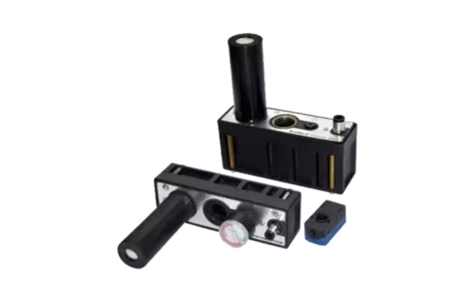
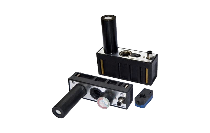 | Compressed Air Driven Vacuum Pumps Compressed Air Driven Vacuum Pumps Kalbro Manufacturing Co. is a trusted Compressed Air Driven Vacuum Pumps manufacturers, suppliers & exporters. View product → |
Frequently asked questions
How does a compressed air jet create vacuum inside an ejector?
Supply air passes through a small nozzle, accelerates into a high-speed jet, and creates a low-pressure zone at the suction port. Process air enters that zone, mixes with the motive air, and exits through the diffuser and exhaust.
Why do multiple ejector stages reach a deeper vacuum?
Each stage lowers the pressure further by evacuating air from the preceding stage. Staging improves ultimate vacuum, but it also increases air-path complexity and requires adequate supply pressure and clean internal passages.
What happens during a compressed air vacuum pump operating cycle?
A start command opens the compressed-air valve, the ejector generates suction, and the process line is evacuated continuously. The controller closes the valve at the stop condition, after which suction decays and the system may admit air through a release or check valve.
How does the load affect suction flow and air consumption?
A large open volume demands high initial suction flow, while a small leak requires lower flow after evacuation. Air consumption depends on supply pressure, ejector design, cycle time, leakage, and how frequently the pump restarts.
Keywords